
Independent five-year Auto-ID study carried out by U.S. Department of Energy.
This Pantex DoE report was made public and presented at the 52nd annual meeting of the Institute of Nuclear Materials Management July 17th, 2011. Details are now released and concludes after extensive testing of many wireless technologies that only one (RuBee) meets all security, intrinsic safety and performance criteria for materials management at Department of Energy.
For Power Point Slides Presented at INMM Meeting click here.
For the full report (PDF in English) click here.
For the full report (PDF in Arabic) click here.
For a brief Arabic Summary click here.
ADVANCED INVENTORY AND MATERIALS MANAGEMENT AT PANTEX
Leesa L. Duckworth
B&W Pantex, LLC
P.O. Box 30020, Amarillo TX 79120-0020
ABSTRACT
This five-year pilot study utilized a stage-gate approach for the identification, analysis, and performance testing of auto-id technology, which could provide a viable foundation for an automated material management system. Over the five-year period, three phases of evaluation were performed, during which a large quantity of various auto-id technologies, including: assorted RF technologies of varying frequencies, infrared, acoustic, magnetic field, and optical tracking technologies, were evaluated against environmental performance criteria designed to simulate the Pantex operating environment. These technologies were measure and compared, ultimately resulting in the identification of a single technology which after extensive testing, appears to hold the capability to meet all of the criteria for a potential materials management foundation.
Traditional methods of material management across the complex include; labor intensive physical inventory, bar coding, and hand scanning, each of which relies on time consuming human interaction and poses many opportunities for data error. Traditional software database systems also provide no solution for data input accuracy resolution, and although they provide very useful data management tools, the resulting reporting is only as accurate as the initial input.
The Advanced Inventory and Materials Management (AIMM) pilot explored the feasibility of auto-id technologies as a potential answer to the identification, tracking, and inventory needs of material assets at the Pantex Plant. This exploration process utilized a stage-gate approach to the evaluation of auto-id technology, and was broken down into three delivery phases:
Phase I (FY08) Identified potential auto-id technologies, completed Technical Security Evaluations (TSE), and conducted performance testing of the most promising commercial technologies available. Identified through the performance testing, the most viable technology for further evaluation in the Pantex environment.
Phase II (FY09) Took the technology selected during the Phase I activities, and 1) evaluated its performance in several different modes and configurations within low risk/minimal-moderate security production support locations, 2) conducted laboratory analysis and evaluation of operating system specifications, and 3) performed initial evaluation of the impacts of an auto-id installation on production areas.
Phase III (FY10/FY11) Continued the evaluation of the previously selected technology by, 1) deploying the technology in a foundational chemical tracking activity, which explored the possibility of receiving tagged chemical materials from an outside vendor, and 2) conduct an operational environment test deployment for tooling in the High Risk/High Security operating areas.
TESTING AND EVALUATION PROCESS
Phase I FY 2006/2007
The first phase of the AIMM project involved the evaluation of various potential auto-id technology options, which included: a variety of the most commercially common RFID, representing a broad range of bandwidth applications; RuBee (Magnetic Auto-id), optical tracking, and several other passive and active tracking technologies, against the unique needs and requirements of the Pantex work environment. Phase I employed the cooperative efforts of KCP, Kansas University (KU) RF test lab, and Oak Ridge National Labs (ORNL), in the identification, testing, and evaluation of possible automated identification solutions against a set of simulated Pantex environmental criteria. These evaluations identified a number of limitations in potential technology contenders, many of which were rendered non-viable for Pantex applications as a result. The report from KCP and the testing conducted at ORNL, resulted in the recommendation of further testing of the RuBee technology, based upon its more accurate function against the simulated operating environment parameters.
Standard electrical field RF technologies demonstrated limited operability in the high metal environment of the Pantex simulation, as well as high levels of failure in the presence of liquids. The RuBee technology is a magnetic field RF technology with little to no electrical field presence. Because RuBee functions in the magnetic field spectrum, it demonstrated much greater performance when placed on metal containers. Additionally, the magnetic field is not inhibited by liquids, making RuBee an optimal candidate for evaluation using liquid chemical. As a result of these recommendations, a TSE evaluation was requested for permission to test RuBee at Pantex. The results of the TSE evaluation were positive and allowed for further testing of RuBee at Pantex. The further evaluation of RuBee also received support from the NNSA RF Working group which hosted a meeting in Albuquerque that year.
The Pantex demonstration/evaluation processes were performed concurrently with ORNL and KCP evaluations, and compiled the interactive feedback of each tester/observer through the use of a User Test Simulation Protocol (ORNL & KCP), final test evaluation reports for KCP and ORNL, and the End User Survey (Pantex). The Phase I deployment pilot included a stand-alone inventory and tracking demonstration and a total of nine, RuBee tagged, classified tooling items. Demonstrations were performed for participants from all levels of plant employment, including: production technicians, maintenance technicians, Security, various levels of Pantex Plant management, and representatives of the Pantex Site Office (PXSO). Each were given a brief description of the existing operational area’s tooling management processes; were asked to fill the simulated role of a technician, and to provide feedback regarding their perceptions as to the operability, user interface, and overall inventory management potential of the RuBee technology from an end user perspective. An End User Survey Report was compiled based upon the responses from observers of the milestone demonstration, and this feedback was used in the development of the new user interface which was later demonstrated in phase III.
Collaboration with the Sandia RF and Electrical Fields evaluations expert, resulted in not only the destructive test evaluation of the RuBee Generation 1 tag, but also provided the project team with Sandia support for the development of a magnetic field analysis formula through the RF Magnetic Field Coupling Analysis (Kenneth Chen, Sandia, May 2008) which had not existed previously. This analysis was utilized by Pantex Systems Engineering and Pantex Authorization Basis (AB) to derive an approach to evaluate potential impacts of the RuBee magnetic field, complete the Hazards Analysis Report (HAR), and to elicit initial Weapons Response from the National Laboratories. According to Mr. Chen’s paper, “Neither the magnetic field from the RuBee portal nor the short-circuit current of the RuBee Tag battery poses any threat to electro-explosive devices (EEDs) in weapons.”
The RuBee technology performed well in the Phase I test evaluations and demonstrated the ability to pass the scrutiny of TSE, Cyber Security, and other high-security/high-risk operational evaluations unique to the Pantex environment. High levels of cooperation were received from the RuBee technology’s vendor, “Visible Assets,” and RuBee was deemed the correct candidate for additional, more comprehensive Phase II test evaluations. The Phase I implementation plan included the groundwork for additional deployment pilots in technically graded approaches or alternate technology solutions required for other work areas. The published Project Plan provided a clear path to ultimate full-scale implementation, if such implementation is deemed suitable after testing is exhausted.
Phase II FY 2008-2009
The Phase II activities focused on the evaluation of the RuBee technology in a multi-location, stand-alone tracking process for tooling in the LA, and the development of requirements for a multi-location chemical tracking application in cooperation with KCP. It also set in motion the laboratory evaluations of RuBee for later test deployment into the high-risk/high-security operational areas.
Unclassified, legacy tooling was used for the Phase II test activities to allow for ease of movement, to prevent negative impacts on production activities, and to allow for storage outside of normally permissible locations. The tooling was marked visibly as RuBee test tooling, inventoried, and entered into the database of expected entry and egress transactions for each of the three Phase II locations. Tools were tracked as they arrived and departed each of the three test locations. All locations were set up as stand alone, temporary test locations, with the hopes of demonstrating RuBee effectiveness in each of these areas, and to identify how to connect those locations to a future RuBee 20/20 server, should a plant-wide deployment come to fruition.
RuBee test tools were assigned specific tag identification numbers, and each location was programmed to expect the presence of those tagged items, so as to evaluate the accuracy of tooling receipt. Tools were moved between each location, and the performance of the RuBee equipment at each location was documented. The equipment testing in this phase of the pilot included RuBee Smart ShelfTM, Smart MatTM, and loop antennas which were used at all project locations. The antenna layout and design were internally conceptualized and were not designed by the RuBee vendor, or optimized for the testing locations through the completion of a localized noise study (also a vendor design activity).
During this testing phase, additional RuBee emanation testing and evaluation were conducted by Pantex Systems Engineering, and Sandia RF and E-Fields experts utilizing a calibrated loop to determine the field strength of the RuBee Antenna in all configurations including the “Smart MatTM”. This testing resulted in the development of a magnetic field formula which was used by Kenneth Chen, Sandia, in the development of a paper released in February 2010, RuBee Smart Mat TM Coupling to Transportation Carts.
Tool tracking testing in Phase II was completed successfully, and the RuBee technology demonstrated a solid level of performance and consistency even when the equipment configuration was not optimal or designed for the selected location or was blocked by other tools.
Phase III FY2010-2011
The third phase of the AIMM Pilot addressed the approval, installation, and testing of a limited location deployment into the high risk/high security operational facilities for tooling tracking, the completion of a chemical tracking pilot which began during Phase II, and the demonstration of a cooperative customer/vendor RuBee tracking activity between Pantex and KCP. As a result of the Phase II tests and evaluation by Sandia and Pantex Systems Engineering, approvals were given for the installation of RuBee equipment. AB Evaluation of the equipment and Unresolved Safety Questions (USQ) were completed, allowing for the installation of RuBee equipment into the personnel and cargo access locations of the target operational facility.
APPROACH/STRATEGY
Chemical Tracking
RuBee equipment was used to identify and track chemical products as they progressed through the Pantex testing and approval process. The performance of the RuBee installation was tested over 10 system cycles, and performed at high levels of accuracy. Demonstrations of these installation locations were conducted for interested parties in departments who have self-identified as potential future auto-id customers.
Tooling Pilot Phase III
The tooling deployment focused on the tracking and inventory of a select set of programmatic tooling. The primary areas of interest involve the personnel and cargo access areas of the test, operational facility. Loop antennas were used to detect tool arrival and departure from both of the Phase III looped locations, and inventory was conducted in the cargo access area, to simulate tooling storage situations. Inventory and tracking reports have were provided through RuBee 20/20 software for the purpose of the pilot, with emphasis on the development of a communication solution to allow the RuBee 20/20 applications to communicate with plant inventory management software.
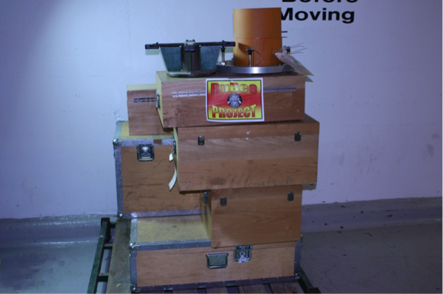
Process tooling (approximately 15 items), was selected for the purpose of this test deployment, with an emphasis on preventing interference with active operations. Tag locations were selected based upon the physical design and/or packaging of the individual tool. Tools which are required to be transported inside boxes had their box tagged, while larger tools which did not have boxes, but provide a base surface that will not interact with operations, were evaluated by Production Tooling Support to determine best tag mounting location. Several of the tools within boxes were tagged also in order to demonstrate tool and container correlation within the RuBee software, and to demonstrate the capability of the RuBee technology to tools within a box. Tooling was piled on a metal pallet and moved into and out of the cargo loop field. Individual tools which could be hand-carried were tested in the personnel access area, simulating the manner in which individual tools are delivered to operating facilities, by production Tooling Material Handlers.
PROJECT EXECUTION AND ACCOMPLISHMENTS
The Phase III Chemical and Tooling pilot obtained required approvals from Systems Engineering, AB, TSE, Cyber Security, and Explosive Safety for the installation testing and evaluation of the RuBee technology in the Zone 12 South MAA. NES approvals are in place, with only the final NES activity remaining. Initial NES meetings have been conducted in preparation for Nuclear Explosive Safety Study (NESS) finalization, and the suggestion has been made by the NNSA NES chair, that the activity would require a limited scope NESS against the Pantex Transportation Safety Analysis Review (SAR) is order to finish their study and approval.
Final Weapons response from the National Laboratories has been requested, and per AB, would result in a change to the Pantex Master Authorization Agreement and Documented Change Proposals (DCPs) for the affected areas.
The Phase III pilots provided the testing and demonstration of RuBee in multiple but connected, single point receiving and inventory locations; this process also allowed for the presentation of a first iteration user interface, based upon the feedback of the earlier Phase I demonstrations, and the needs identified in the Potential Future users Surveys.
ONGOING RUBEE EVALUATIONS
With the success delivered by the AIMM pilot, the foundation for the next logical testing of the RuBee technology has already been established, and had received funding from the Pantex Plant Directed Research, Development and Demonstration (PDRD). This next step involves the testing and evaluation of a fully enabled and synchronized RuBee facility at Pantex. This project will be conducted at the Pantex Medical facility, and seeks to demonstrate facility level material control performance features,that mimic the needs, and can be generalized for high risk/high security facilities across the plant.
REFERENCES
1.Letter from K. C. Chen to M. K. Fuentes, Subject: RF Magnetic Field Coupling Analysis, May 27, 2008.
2.Letter from K. C. Chen to D. A. Hoke, Subject: RuBee Smart MatTM Coupling to Transportation Carts, February 25, 2010.
3.K.C. Chen “EMR Coupling to Transportation Carts and Other Containers,” ESD-145, February 23, 2011.